Configuring LAG on PIXERA four and PIXERA one/two Gen.2
On a PIXERA four and PIXERA one/two Gen.2 servers, Link Aggregation can be activated using the PROSet Tool provided by Intel.
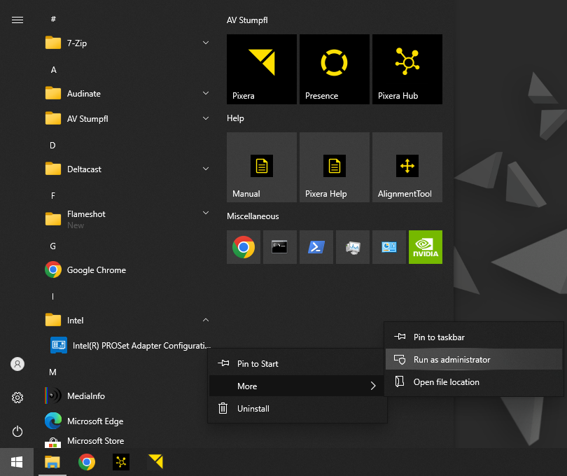
To do so start the Intel PROSet Adapter Configuration Tool program as an administrator.

Select the physical network controller, on the left side, on which you want to create a new LAG and open the tab “Teaming/VLAN”. There you can create new Teams.
Press the “Create Team” button to create a new Team. Select the network adapters that should be member of the team and press “Next”.
Choose a name for the team and the LACP type you want to use and press “Next”.
Possible LACP Types are:
Adapter Fault Tolerance
Adapter Fault Tolerance (AFT) provides redundancy through automatic failovers from an active adapter to a standby adapter in the case of switch port, cable, or adapter failure.
Adaptive Load Balancing
Adaptive Load Balancing (ALB) provides transmit traffic load balancing and fault tolerance in the event of switch port, cable, or adapter failure.
IEEE 802.3ad Dynamic Link Aggregation
IEEE 802.3ad Dynamic Link Aggregation is an IEEE standard for increasing throughput between switches or a server and switch. This is accomplished by dynamically bundling or channeling several ports together and showing them as a single link using Link Aggregation Control Protocol (LACP). This increases the total bandwidth for the link and provides fault-tolerance in the event of switch port, cable, or adapters failure.
Switch Fault Tolerance
Switch Fault Tolerance (SFT) provides redundancy across switches. An adapter connected to one switch will automatically failover to a standby adapter connected to a different switch in the event of a switch, switch port, cable, or adapter failure.
Static Link Aggregation
Static Link Aggregation (SLA) is a performance technology developed to increase throughput between switches or a server and switch. This is accomplished by bundling or channeling several ports together and showing them as a single link. This increases the total bandwidth for the link and provides fault- tolerance in the event of a switch port, cable, or adapter failure.
Note:
Please note that the network infrastructure behind the PIXERA server must also be adapted. This means, for example, that the switch behind a PIXERA Server LAG located in the LAG must also be configured so that it functions correctly.
Select the primary and secondary adapter for the team and press finish.
 Contact Us


